dec
15
dec
12
Oplossing voor de oplader van de RETEVIS RT3 en MD380-390
Er schijnt een probleem te zijn met het opladen van bovengenoemde portofoons. De te hoge spanning van de lader zorgt er voor dat de batterij vroegtijdig kan overlijden. Guenter DK8DX voorziet ons van een oplossing!
RT3 modifications
Disclaimer
Proceed at your own risk ! The modifications on this page may not apply to your radio, and the findings descibed here may only apply to a single unit. The author won’t be liable for anything at all, blah, blah.. (consider this as the usual disclaimer. It also applies to the description of firmware modifications, and to any link you may find on this webpage).
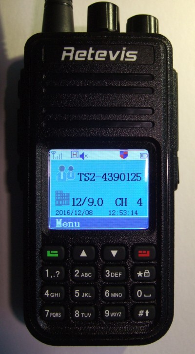 The Retevis RT3 is a monoband handheld transceiver for DMR (digital voice) and analog FM. It is almost identical to the Tytera MD-380. You certainly already know the radio (since you visited this page), where to find the programming software, and how to prepare a suitable “codeplug” (configuration) to operate via repeaters in your area.
If you don’t, ask the big brother for “Retevis RT3” or “Tytera MD-380”. Don’t miss ham-dmr.de, the codeplugs by DK4WN, the descriptions by DG9VH, the introduction You and your MD-380 by AC2SN (known as ladyada), the programming software at Retevis and VA3XPR, and (for experienced users and developers) the ‘Experimental’ firmware by KK4VCZ.
Contents
- Modified “8.4 V” charger to keep the cell voltage below 4.2 V
- “Exposed” electrical contacts on the LiIon battery
- Continuous weak, additional backlight
- Upgrading from Firmware “D002.xxx” to “D003.020”
- Installing KK4VCZ’s ‘Experimental’ firmware
“8.4 V” Battery Charger: Modified to avoid overcharging the LiIon battery
The RT3 was shipped with several accessories, including a charger for the radio’s 7.4 V LiIon battery. That charger has a bi-colour LED on the front side, which should indicate ‘red’ while charging, and ‘green’ when fully charged.
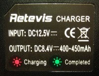 According to the label, charging current should be around 400 to 450 mA. Thus a 2000 mAh LiIon accumulator (2 cells in series, thus really a “battery”) should have been charged within 5 hours. My expectation was the LED would switch from red to green after this time.
But it didn’t. In fact, the LED never turned green. After removing the radio from the charger, and checking the voltage directly at the battery terminals (see next chapter), almost 8.6 Volts were measured. Ooops ! That’s a bit much for two LiIon cells in series !
In the interest of lifetime, the voltage for a single cell should never exceed 4.2 Volts. More voltage will not “fill in” significant extra charge, but reduce the battery’s life time. So the charger was modified as described below, to achieve a ‘healthier’ max output voltage of 8.4 V (for two cells in series).
The principle is easy. The charger shipped with the RT3 uses an MC34063 in a switching-mode step-down converter configuration.
This IC uses an internal reference voltage of 1.25 V, which is compared against the charger’s output voltage (“8.4” V) divided down to 1.25 V. The voltage divider consists of resistors R3A (33 kOhm) paralleled with R3B (1.8 kOhm), resulting in 1.707 kOhm, and R4 (10 kOhm) in series.
                                       ____
                      R4         ,----|____|----|
                      ____       |  R3A : 33 kOhm
      +"8.4" V  -----|____|------*
     (battery                    |     ____
      voltage)       10 kOhm     *----|____|----|
                                 |  R3B : 1.8 kOhm
                                \|/
                              1.25 V (to MC34063 control input, pin 5)
The regulator’s theoretic output voltage with the original components (shown above) is
1.25 V * ( 1 + 10 kOhm / 1.707 kOhm ) = 8.57 V .
This ‘surprisingly high’ voltage for a 2-cell LiIon battery pack was confirmed by measuring it at the battery after removing it from the charger !
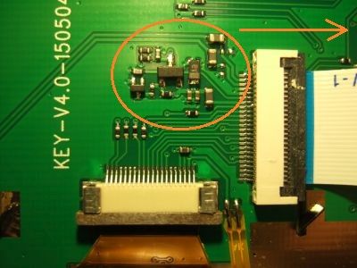
Almost 8.6 V is quite a lot for two LiIon cells in series, especially if the radio was kept in the charger for longer than necessary. So how to reduce the charger’s maximum output voltage ? The photo below shows the charger’s PCB, component side, with the originally populated resistors (R3A, R3B, R4 labelled in white), and a few voltages measured when the battery was fully charged (but the LED was still ‘RED’ when it should have been ‘GREEN’).
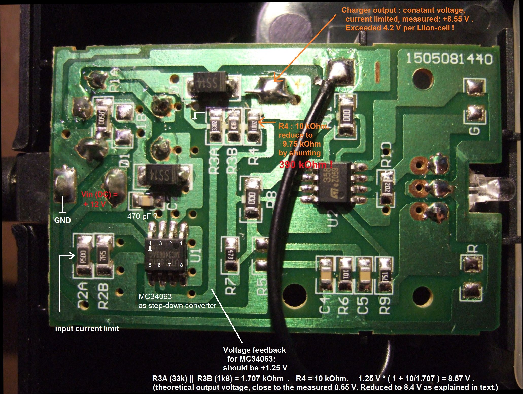
(Click on image to magnify)
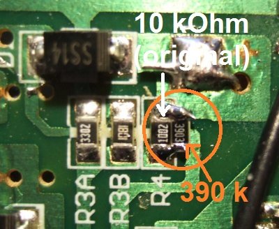 A simple method to bring down the maximum output voltage to 8.4 V is shunting R4 (10 kOhm ‘original’) with a 390 kOhm resistor.
The ‘paralleled’ resistance is
1 / ( 1/10kOhm + 1/390kOhm) = 9.75 kOhm, so with the modified voltage divider, the theoretic output voltage should be:
1.25 V * ( 1 + 9.75 kOhm / 1.707 kOhm ) = 8.39 V .
That’s 4.19 Volts per LiIon cell – ok. And indeed, with this modification, the battery stopped ‘drawing current’ when fully charged, and the LED turned green after a couple of hours (btw, that’s what the LM358 is for, visible in the right half of the photo above). Voila !
An even simpler alternative (instead of ‘shunting’ R4) would be to remove the 33 kOhm resistor (R3A in the photo shown above).
The theoretic output voltage would then be:
1.25 V * ( 1 + 10 kOhm [R4] / 1.8 kOhm [R3B] ) = 8.19 V .
The two-cell LiIon battery would possibly not be “fully” charged very quickly with this voltage, but forgetting to remove the radio from the charger would do even less harm then.
Exposed ‘hot’ LiIon battery contacts
The LiIon battery’s charger contacts can ‘provide current’ during normal operation !
Both the LiIon battery, and the charger appear to have THREE CONNECTORS, but the center connector isn’t connected anywhere (inside the charger). There doesn’t appear to be a ‘smart’ protection circuit inside the battery to protect it from excessive loads.
THIS APPLIES NOT ONLY TO THE CONNECTORS THAT ‘FEED THE RADIO’ (those not exposed during normal use),
BUT ALSO TO THE CONNECTORS FOR THE CHARGER, which are exposed when operating the radio !
Remember this when dropping the RT3 (or MD-380) into your pocket along with the bundle of keys, or other metal objects
– a short across the battery’s outer, exposed contacts will possibly ruin it, or even worse.
I didn’t want to test how many amps can be drawn from the exposed contacts on the backside of the transceiver.
At least, the exposed contacts could be abused to power an ancient filament lamp:
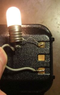
Warning: Never, ever, deliberately short these contacts. There may be, or maybe not, a self-resetting fuse inside the battery, but you really don’t want to find this out “the hard way” !
Continuous weak, additional backlight
By default, the backlight is turned off completely after a programmable timeout. That’s not nice, because when this purely transmissive display isn’t illuminated from the background, it’s completely unreadable.
A ‘permanently’ lit display, with reduced intensity but still easily visible, can be realized with a simple 220 Ohm resistor connected between collector and emitter of the backlight-switching transistor on the display-/”key”-board.
For reasons only the developers of the original firmware will know, the LCD (TFT) itself is not powered down. So it makes perfect sense to keep the backlight on, “deeply dimmed”. The modification shown below is made on the display board, not on the CPU/RF board:
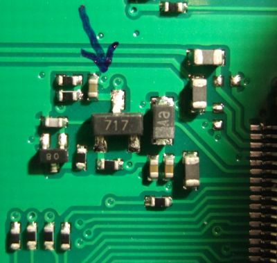
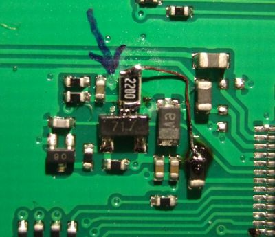
Left: Display PCB. Middle: Original backlight switch. Right: Modified backlight for “continuous ambient light”.
Click on any image to magnify.
The blue arrow points to the transistor’s collector. The thin wire on the right photo connects the upper end of the 220 Ohm (SMD) transistor to the 3.3 V supply for the display. When the backlight is on, there are 3.3 Volts on the collector. When off, 0 Volts. The forward voltage of the white LEDs is somewhere around 2.9 V, so the 220 Ohm resistor feeds as continuous current of less than 2 mA to the LEDs, which was enough to read everything on the display in a darkened room (or outdoors). Even the keys were very dimly illuminated – barely visible but enough to operate them in complete darkness – nice ! The additional power consumption from the battery is neglectable.
Note for developers: The backlight is controlled via pin PC6 by the CPU (STM32F405). This pin can possibly be reconfigured as PWM (pulse width modulator) instead of GPIO, but at the time of this writing it was unknown if Timer8 or Timer3 are still available for this purpose. Having the backlight completely software-controllable (with different intensity settings for “idle” and “active”) would be great…
dec
10
Review van de CS589 portofoon
dec
09
PD-AR685 GPS UHF is leverbaar in Nederland
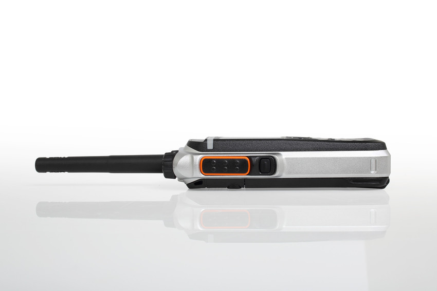
Hytera PD-AR685 GPS UHF
Deze portofoon is speciaal voor de radioamateur. Het verschil is dat deze AR uitvoering geen “Man Down” functie en encryptie heeft, features die niet echt gemist zullen worden door radioamateurs. Een ander verschil is de prijs: voor de PD-685 GPS UHF betaal je € 453 en de nieuwe PD-AR685 GPS UHF kost € 309. Een flink prijsverschil!
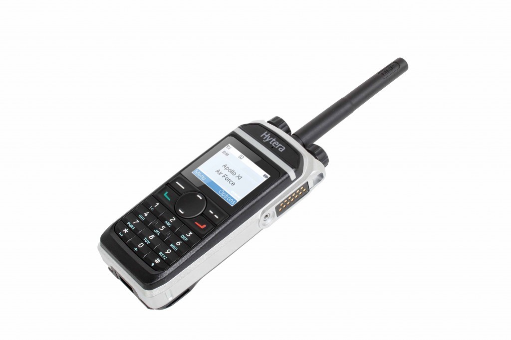 The flagship of the PD6 series from Hytera.
The PD685/PD685G handheld radio is the ideal companion for migrating to digital mobile radio. As a member of Hytera’s PD6 series, the PD685/PD685G has a lightweight metal case and supports digital and analog mobile radio. Thanks to its full keypad, three programmable keys, and its bright LCD display, the PD685/PD685G offers a great user experience.
Small, lightweight and thin
The handheld radios of the PD6 series are only 27 mm deep, making them particularly compact. They are encased in a high-quality aluminum metal frame and with a weight of only 310 g (PD685) comfortable and easy to carry for long operations.
Long battery service life
With the lithium-ion battery with 1500 mAh included in the delivery, the PD685/PD685G achieves an operating time in digital operation of at least 16 hours. With the optionally available 2000-mAh battery, it will even be 20 hours.
Improved utilization of the frequency spectrum
The PD685/PD685G can be operated in TDMA Direct Mode and Pseudo Trunking. This assignment of the available bandwidth with double the number of channels leads to a significant easing of the increasing shortage of frequencies in the operation of DMR mobile radio systems compared to analog mobile radio systems.
Expanded frequency range
The frequency range in UHF stretches from 400 MHz to 527 MHz.
Support of analog and digital mobile radio
The PD685/PD685G was developed in compliance with the ETSI mobile radio standard Digital Mobile Radio (DMR). The handheld radios support the conventional DMR operation and can also be operated in analog mode. That makes the PD685/PD685G the ideal companion for the move to digital mobile radio.
Additional functions (selection)
Every radio of the PD6 series is also available with GPS. Variants with GPS support GIS applications, such as AVL and telemetry.
Encryption with the encryption algorithm ARC4 (40 bit) in accordance with DMRA or with optional algorithms AES128 and AES256 (128 and 256 bit)
Expansion interface for applications
Man-down function (optional)
Leasing function
Versatile voice calls: Individual call, group call, broadcast call, emergency call
** De laatste firmware updates, codeplug software en codepluggen kunt u downloaden op ham-dmr.nl
In the box:
– Portable
– Desktop charger + adaptor
– Antenna
– Clip
– Cord
– Accu
Deze porto is verkrijgbaar bij HAMSHOP.
dec
08
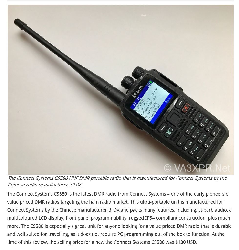
Connect Systems nieuws
I thought I would give a status update of what Connect Systems is doing.
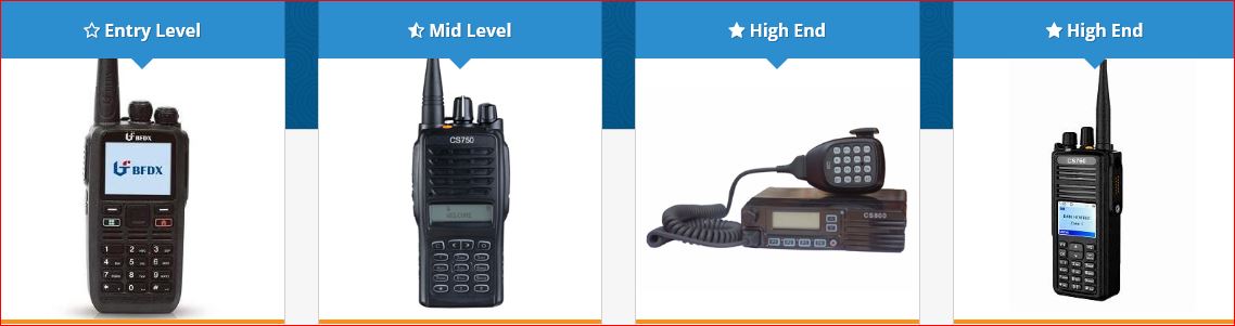
CS580: This radio was designed to be in direct competition to the MD380 radio but have the advantage of being much easier to use because of a few new features we added. We sold over 100 radios before it was officially released and we have about 200 radios left before we have to order more. It takes at least 30 days from placing an order to receiving more radios. We have already received follow on orders from some of the people who have ordered the first batch of radios. It cost $130 each.
CS750: We reduced the price from $239 to $180. At this price, it is a competitor to the Tytera products but you get a better radio with more features. After the CS760 is stabilized, we will be adding more features to this radio as well as fixing any remaining problems.
CS760: This is the follow on to the CS750 series of radios. Besides having the features of the CS750, it has optional Bluetooth, GPS, Man Down, and vibrator. Its IP67 rated (waterproof) and has a color display. It will have the ability to be compliant with ETSI Standard Tier III. Being a new radio with new features now and more new features in the future, you can expect this radio to have frequent firmware updates both to fix bugs and to add new features. It was originally scheduled to ship December 1, then December 10, and now December 19. The basic radio cost $299 and with all the options it cost $399.
CS800: This is our single band UHF mobile (Available in VHF). After the CS760 is stabilized, we will be adding more features to this radio as well as fixing any remaining problems.
CS800D: This is a dual band CS800. I expect the VHF band to be the same as the CS801 and the UHF band to be extended to 512 MHz. It is initially going to be released as an amateur product but later we will get it part 90 certified. We do not have our cost yet but I am hoping the selling price will be $100 more than the single band CS800. We have preliminary schematics and we have a target of getting a working sample shipped by January 23, 2017 to show at the various amateur shows and production starting about two months later.
CS108G+: This is a Xiegu X108G with custom firmware to include a spectrum analyzer and an ID Timer. It covers all the HAM bands from 160 meters to 10 meters. We expect to get our first shipment next week.
CS7000/CS8000: This is a single band multi-protocol (DMR, DSTAR, Analog, and others) radio. We are still working on it but I will not give a definite date for initial shipments.
Jerry Wanger KK6LFS